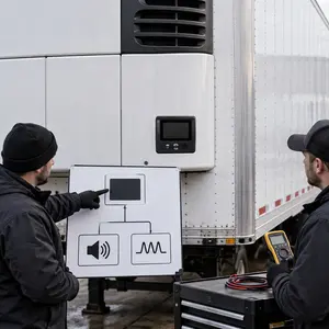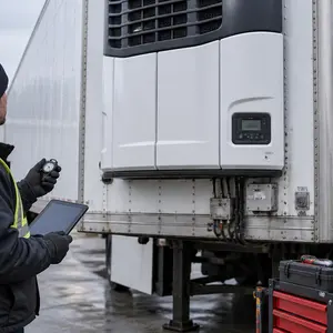


A refrigerated trailer can miss temperature in several ways. The box may never pull down after loading, may reach the target and drift upward, may recover slowly after doors close, or may show a growing difference between the requested setpoint and measured return air. Each pattern supplies different evidence for Thermo King or Carrier service.
A warm reading does not identify a refrigerant leak, compressor, sensor or controller failure by itself. Useful diagnosis combines the operating sequence, complete controller state, supply and return temperature behavior, airflow, cargo condition and trailer environment. Cargo decisions remain with the responsible fleet, shipper, receiver or other authorized party while the equipment is evaluated.
Define what “not cooling” means on this load
Record whether the unit is expected to remove product heat, maintain already conditioned cargo or protect an empty trailer before loading. Note the required operating mode and setpoint supplied by the responsible party. The technician should not invent a commodity setting or change a shipper instruction to make the display look closer to target.
Describe the failure in time. State when the trailer was loaded or doors were closed, the first recorded box temperature, the best temperature reached, when the rise began and the latest verified reading. A sequence distinguishes slow pull-down from a sudden loss after otherwise stable operation.
Use setpoint, return air and supply air correctly
The setpoint is the controller request. Return air represents air coming back from the load area to the evaporator, while supply air is delivered from the unit into the trailer. Their availability and display names depend on the controller and configuration, so photographs should capture the full screen and labels shown by the actual unit.
One number cannot describe the complete box. Compare readings at recorded times and identify whether they came from the unit controller, a fleet telematics system, an independent logger or a handheld instrument. Do not combine measurements from different locations into one unlabeled temperature.
Preserve Thermo King or Carrier controller evidence
Photograph the full HMI before changing mode, setpoint or alarm history. Include active alarms, stored events, defrost state and any visible operating status. A cropped code number can hide the controller family, surrounding messages and the state that existed when temperature began to move.
Alarm meaning, severity and unit response depend on model, controller and documentation revision. A code directs a test path; it does not automatically name the part to replace or establish that the detected condition still exists. If the display changes during the event, a short video can preserve the order better than several disconnected photographs.
Report operating mode and recent transitions
State whether the unit was in continuous run, start-stop or another permitted mode, and whether it was cooling, heating, defrosting or waiting at the time of the observation. Note every recent transition, including startup, defrost, door opening, loading and return to cooling.
A temporary temperature change during a documented operating transition must be interpreted with the correct model procedure and time sequence. It is different from a steady loss while the controller reports active cooling. Avoid forcing repeated mode changes merely to see whether one makes the alarm disappear.
Confirm cargo and loading conditions
Provide the general cargo category, whether product entered at the required temperature, the loading time and any known internal probe or logger locations. Service personnel need this context to understand the heat load and air path; they do not determine cargo acceptance or disposition.
Record whether pallets, bulkheads, curtains or packaging block the supply path or return-air opening. Do not enter a loaded trailer or move cargo without authorization and site controls. Photographs taken safely from the doorway can document clearances without exposing personnel to moving equipment or temperature hazards.
Account for doors, seals and trailer-envelope heat
List the duration and frequency of recent door openings. Inspect visible rear-door seals, hinges, latches, side or roof damage and light entering through a closed opening where safe. Air leakage and warm infiltration can increase load even when the refrigeration unit continues to operate.
Trailer-envelope evidence does not eliminate the need to test the unit. A damaged seal may coexist with weak refrigeration performance, and a sound-looking door does not prove the insulated body is intact after impact, repair or long service. The final diagnosis separates observed trailer conditions from measured unit findings.
Evaluate accessible evaporator airflow
The evaporator moves conditioned air through the cargo space. With personnel clear of automatic fans, the technician observes accessible inlet and outlet condition, air movement, ice or water evidence and any visible obstruction. Exact fan operation and access procedure come from the identified equipment documentation.
Low airflow can result from more than one condition, including blocked load paths, fan or electrical problems, coil restriction, icing or control state. Never reach through a grille or remove a guard from an enabled unit. An apparent airflow problem still requires measurements before a component is authorized.
Inspect the exterior condenser and trailer-front unit
At the front of the trailer, record the condition of the closed housing, condenser opening, visible fan area, mounting and surrounding clearance. Road debris, contamination or impact can affect heat rejection under a sustained refrigeration load. Cleaning must protect coil fins, electrical equipment and the trailer wall.
The refrigeration unit belongs high on the trailer front wall. A tractor-frame APU serves a different system and cannot explain cargo-box temperature, evaporator airflow or a controller event recorded by the trailer unit. Keeping both equipment types separate in photographs prevents the wrong asset from being dispatched or diagnosed.
Check electrical supply and component response
The technician verifies the applicable battery and charging behavior, cables, grounds, protection devices and commanded component response. Electrical checks are performed under the relevant operating condition because an unloaded reading may not reveal a connection or supply problem.
A powered display proves that the controller has some electrical supply. It does not prove that every fan, valve, sensor, clutch, motor or other controlled component is operating as requested. Test points, expected values and isolation procedures remain model-specific.
Diagnose the refrigerant circuit with measured evidence
Refrigeration diagnosis can include temperature relationships, pressure observations, leak evidence and controlled component tests appropriate to the model and ambient condition. Refrigerant type, charge procedure and service connections must come from the equipment data and applicable documentation.
Do not add refrigerant because the box is warm. Incorrect charge can create another failure and can hide the original leak or airflow problem. Leak repair, evacuation, charging and component decisions follow verified findings and qualified handling procedures.
Distinguish loss of capacity from loss of operation
A unit may continue running while delivered cooling capacity falls, or it may stop one or more required functions entirely. Record engine or electric-power state, fan behavior, controller request and how supply temperature changes. The difference directs the next measurement without assigning a premature cause.
If the unit shuts down, loses controller power or fails to restart, preserve that sequence and route it through the appropriate diagnostic scope with the elapsed runtime and preceding controller state. Temperature loss remains important evidence, but the shutdown or no-start condition requires its own controlled investigation.
Interpret defrost and icing as a sequence
Capture when defrost began and ended, what the controller displayed, whether airflow changed and how temperature behaved afterward. Visible ice, repeated defrost or water in an unusual location can support further inspection but does not establish one universal fault.
Do not chip ice from the evaporator or force a defrost sequence without the applicable procedure. Mechanical damage can convert a diagnostic problem into a coil or wiring repair. A recurring condition may need sufficient runtime to reproduce after the coil has returned to a known state.
Track intermittent temperature loss over enough time
An intermittent complaint can disappear during a short service visit. Align temperature trend, controller events, operating mode, door activity and elapsed runtime on one timeline. If telematics or logger data is available, preserve its source and time zone so events can be compared accurately.
State the limits of the observation. A unit that operates for twenty minutes has not necessarily disproved a failure that normally returns after several hours or after the next defrost. The work record should identify what was reproduced and what remains conditional.
Stop unsafe inspection and protect the cargo process
Stop operation or inspection when there is smoke, electrical heating, refrigerant exposure concern, damaged rotating equipment, fuel leakage or another immediate hazard. Keep people clear of the trailer front, prevent an automatic restart and use the facility, fleet and emergency procedures appropriate to the location.
When cargo temperature is outside the required range or continues to rise, notify the authorized cargo contact promptly with measured facts. Service personnel report equipment state and repair findings. They do not declare product safe, change custody requirements or promise that a later pull-down reverses prior exposure.
Choose mobile diagnosis or controlled shop work
Mobile service can begin with asset identification, controller history, accessible electrical and airflow checks, trailer observations and safe operating measurements. The location needs legal parking, permission, clearance at the trailer front and protection from traffic or active dock operations.
Controlled shop conditions may be required for refrigerant recovery, guarded component access, extended operation, electrical isolation or testing that cannot be done safely in weather. The service path follows access and technical requirements, with the reason for relocation documented.
Information to send before dispatch
- Asset: trailer number, refrigeration-unit make, model, serial information and complete controller photograph.
- Temperature record: setpoint, return and supply readings with times and measurement sources.
- Sequence: startup, pull-down, stable period, temperature rise, defrost, shutdown or restart events.
- Operating context: selected operating mode, ambient weather, door activity, defrost timing and approximate time since loading or the last prolonged opening.
- Cargo context: general product category, reported loading temperature and authorized contact.
- Physical observations: airflow, ice, water, odor, unusual sound, visible damage or leakage from a safe position.
- Recent work: system serviced, date and reported result.
- Location: Illinois route or facility, direction of travel, safe parking and access contact.
These details help select the correct technician, references and equipment. They also prevent a trailer-envelope or cargo-loading issue from being hidden inside a one-line refrigeration work order.
Verify temperature response after authorized work
Repeat the agreed mode and setpoint under documented conditions. Record controller state, supply and return behavior, airflow, ambient condition and box-temperature trend for a period appropriate to the original complaint. A replaced component alone is not a performance result.
If the trailer is empty, recently loaded or exposed to repeated door openings, say so in the closeout. Verification distinguishes measured unit response from a promise about every future cargo load. Any remaining intermittent condition or trailer issue is documented for follow-up.
Reefer temperature-loss diagnosis across Illinois
Chicago is the service base, with Thermo King and Carrier temperature-loss diagnosis coordinated across Illinois according to unit location, safe access, cargo situation and required test conditions. Highway, truck-stop, fleet-yard, dock and distribution-center calls need accurate placement and site-contact information.
Planned fleet work in nearby states, including Indiana, may be arranged after travel, access and scope are agreed. That planned service does not create automatic emergency coverage outside Illinois or a universal arrival-time promise.